PDK Distance sensor problems
How does the PDK distance sensor work?
The transmission has 4 shift rods. Each shift rod can select two gears. In the central position there is no gear selected. When a shift rod is moved one way it engages a gear, and if moved the other direction the other gear is engaged. This is exactly the same as what happens when you move the gear lever in a manual transmission.
To engage a gear the shift rod needs to move approximately 8.5mm from the central position. So the full travel of a shift rod from one gear engagement to the other is twice this, approximately 17mm. The distance sensor needs to accurately measure the position of the shift rod over this range of movement.
Each shift rod has a magnet attached to it. The distance sensor accurately measures the position of this magnet so the transmission control unit (TCU) knows exactly the position of each shift rod, as this is essential for transmission operation. With there being four shift rods (with a magnet each), there are four separate channels on the distance sensor that are constantly telling the TCU the position of each shift rod.

The distance sensor uses a 5V source provided by the TCU. The four distance sensor channels receive the same voltage supply and ground, and a single output for each sensor channel.
The electrical output signal provided by each distance sensor channel is a square wave with a duty factor (duty cycle) that indicates the shift rod magnet position.
A square wave looks like below with three examples given. The duty factor is the percentage of the pulse width when compared to the full wavelength.

If a shift rod is central with no gear engaged, the signal duty factor will be approximately 50%. If a gear is engaged the signal will be close to 20% with one gear engaged, and 80% with the other gear engaged.
Note that in PIWIS and other diagnostics it gives a distance (mm, inches) for each shift rod position. This is just an interpretation by PIWIS of the signal duty factor. This is done because a distance is far easier to interpret by someone using the diagnostic program than duty factor. The TCU however is using duty factor to know the position of each shift rod.
I often have people ask what the correct distances are. The OEM sensor is very consistent in output due to the method it uses to determine distances. I would expect to see distances with an OEM sensor of 7.0 – 8.5mm with a gear engaged, and less than 1.0mm when central. The window for the TCU to consider a distance to be valid is much wider than this, beyond 11mm with a gear engaged. If I saw this with an OEM sensor I would be concerned, but not so much with an aftermarket sensor, as these often use a different detection system. More diagnosis would be needed to determine if the sensor was having problems.
An OEM distance sensor that is working correctly and detecting a magnet will always give a duty factor output of between 10% and 90%. If working correctly it will never go outside of this range. The TCU will always assume any signal it receives within this 10-90% range is valid and correct.
Indications of a working PDK distance sensor
1731, 1732, 1733, 1734 fault codes (distance sensor channel failed)
If the duty factor goes outside of the 10-90% limits, it will give a 173x code, with the x being the channel on which the failure has occurred. For example, a 1732 code means that the output on channel 2 has gone outside the range of 10-90%. This means the sensor channel has failed.
Most often the sensor channel will give a 0% output. In PIWIS, this will be shown as a distance of approximately + or - 13.75mm depending on the transmission type and channel.
There is another failure mode where the channel is online, but unable to detect a magnet. In this case the OEM sensor gives an output of 95% duty factor. This is seen in PIWIS as a distance of approximately + or - 12.75mm depending on the transmission type and channel.
In either case the sensor has failed and needs to be replaced.
1735, 1736, 1737, 1738 fault codes
These codes were introduced with the 991/981 models, and denote a very short transient excursion outside the 10-90% range.
Often these 1731-8 faults (and other faults) are intermittent. When the incorrect signal is detected by the TCU the transmission will go into limp mode. If the car is stopped, and engine stopped and restarted, if the sensor signal is OK the car will drive fine until the bad sensor signal is detected again.
Intermittent failures
The distance sensor and pressure sensors are supplied with the same 5V from the TCU. If this is found to be incorrect (outside of range 4.5-5.5V), it will give a 1706 fault.
Most often this is due to an internal short that has developed inside the distance sensor. This internal short circuit allows too much current to pass through the TCU. The TCU response to this is for the voltage to be lowered below 4.5V, and hence the fault. This is a common fault of the OEM distance sensor.
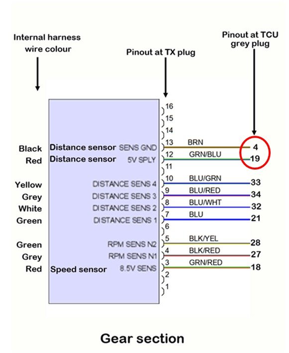
Standard distance sensor supply/ground resistance is approximately 133 k Ohm (pins 4/19 on grey plug at the TCU).
Failed sensor resistance is much less than this. In the order of 100 Ohm. The low resistance draws too much power from the TCU and drops the voltage.
How to diagnose?
1. Disconnect the transmission plug with PIWIS attached and see if voltage recovers to correct reading.
2. Also check the sensor resistance.
How to conduct tests:
1. With PIWIS attached (ignition on, engine off), and showing the 5V supply voltage (the error will be present when the voltage is below 4.5V), disconnect the plug at the transmission that goes to the distance sensor and speed sensor. There are two plugs going to the PDK. Disconnect the lower one that is further from the engine. Normal 5V supply is often slightly lower than 5V, maybe 4.95V.
Does the voltage recover to 5V with the plug disconnected? If it recovers then the distance sensor is at fault. You will get a large number of distance and speed sensor codes that can be deleted later after the plug is connected again.
2. Ignition OFF and remove the grey plug at the TCU. Measure the resistance across the power supply/ground (pins 4/19 in image below). Good OEM sensor resistance is about 133 k Ohm. Well less than this indicates a failed sensor that has developed an internal short and is dragging down the voltage.
Occasionally it’s not the distance sensor and is the TCU itself that has developed a fault. This happened on one occasion that I know of, and the individual found someone to replace the individual component on the TCU circuit board that creates the 5V supply.
1706 (incorrect 5V supply)
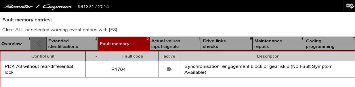
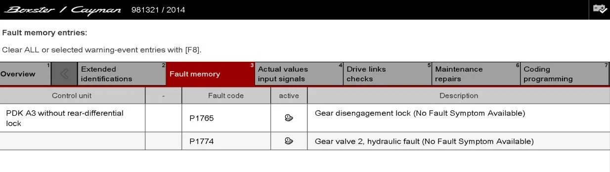
1764 and 1765 codes. Engagement lock/Disengagement lock.
What do these mean?
1764: The transmission has attempted to engage a gear and is unable to do so.
The TCU can command a few responses to this depending on the situation. It may continue attempting the same gear selection, or skip to the next gear it finds with a good reported position. But the reason for the problem is the same, that being the inability to engage a gear correctly. This means that the distance (duty factor) the TCU is looking for when a gear is engaged is incorrect.
1765: The transmission has attempted to disengage a gear to the central position and is unable to do so.
This means that the distance (duty factor) the TCU is looking for when a shift rod is centralised is incorrect.
The Porsche flow charts make it seem like the 1764 and 1765 are a valve body or physical transmission problem, but this is most often not the case. It’s most often a failing distance sensor.
If the OEM sensor output remains within the 10-90% range the TCU considers it to be valid and correct. It has no way of determining if the sensor output is correctly responding to shift rod position, so the assumption is that it’s correct. So when a gear is engaged/disengaged, the TCU thinks the sensor output is correct, and concludes the fault is elsewhere in the transmission.
Often faults for the gear shift valves being stuck (1771, 1772, 1773, 1774) are flagged at the same time. This again is due to the TCU thinking the problem is elsewhere in the transmission rather than the failing distance sensor.
Many people have replaced valve bodies for this problem, only to have the fault remain. Replacing the distance sensor then does fix the problem.
The images below were created by deliberately altering distance sensor outputs to induce the faults, with the transmission otherwise being fully working. When the deliberate sensor programming faults were restored to normal, these faults immediately disappeared and the transmission worked perfectly.