
PDK Diagnosis information
Click on the buttons below for more information relating to each topic
These pages contain information that has been accumulated over multiple years when working with individuals and workshops through their PDK problems. It is only relevant for the 911 (7 speed PDK), Boxster or Cayman platforms.
I’ve done the best job I can of testing and checking all of the information provided, but due to the nature of PDK problems I clearly can’t guarantee that this information will work for you for every circumstance. You also might notice that some of the information provided contradicts fault information in the Porsche official documents. This is due to experience showing that the Porsche documents aren’t always correct.
It is important that you spend time understanding the information provided here and elsewhere, and then diagnose accurately for the best outcome.
Important: The fault codes I refer to are for the 981/991 platform. The 987/997 fault codes are a grouping, with many faults falling under the single fault code. In this case, the accompanying text must be read to identify the fault correctly.
eg. In the 987/997, the P0730 code has 10 individual faults under this heading, including ‘gear ratio monitoring’, ‘brake light switch failure’, and ‘TCU internal fault’. But for the 981/991, each of these will have an individual code, such as P0731 for ‘gear ratio monitoring’.
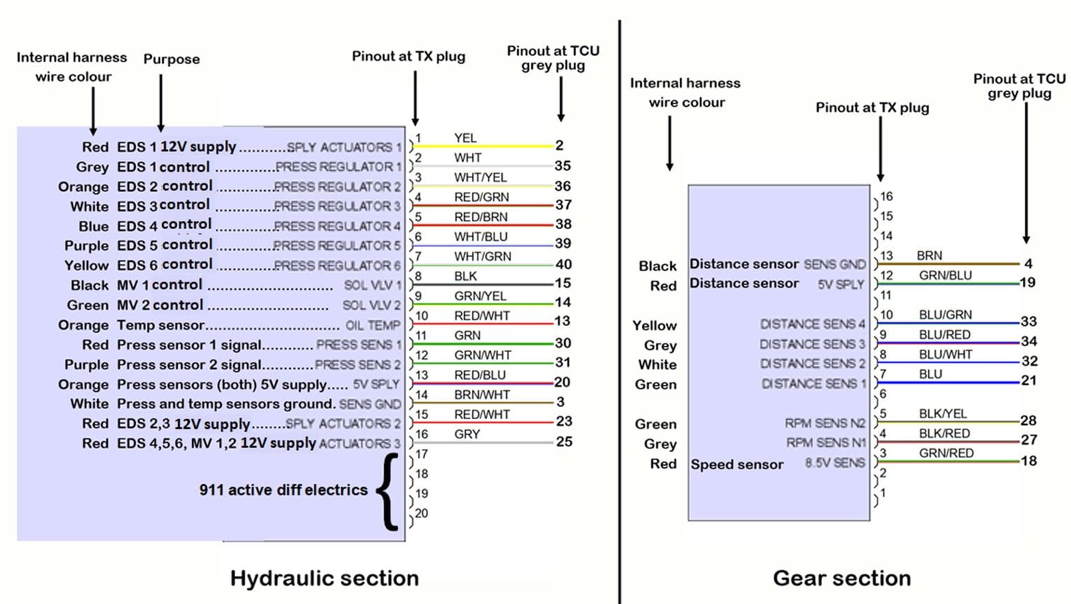
Below is the relevant portion of the wiring diagram with mark-ups that make it simpler to understand each part. This is from the 981 Boxster wiring diagram. For other models the wire colours might differ but the pinouts should be correct. It doesn’t include the pinouts for the 911 active differential. Please refer to the wiring diagram of the model in question prior to conducting tests.
Overall PDK transmission control unit wiring diagram
The TCU is located at the left of the rear luggage compartment in the Boxster or Cayman. For the 911 the TCU is located under the right rear seat.
All sensors are on the plug with the grey shroud at the TCU. The grey shroud can be easily removed so you can then reinsert the individual plug housings into the TCU for back probing and sensor testing. This is for testing of sensor outputs when connected to the TCU and operating.
If you are testing sensor resistances, ensure you have the plug removed from the TCU so you aren’t testing the sensor resistances as well as the TCU at the same time.