
PDK Solenoid information
The solenoids and valve body seem to be very robust, with few faults reported. If you do think you are having problems, the information below may be of some assistance.
Basics of solenoid operation
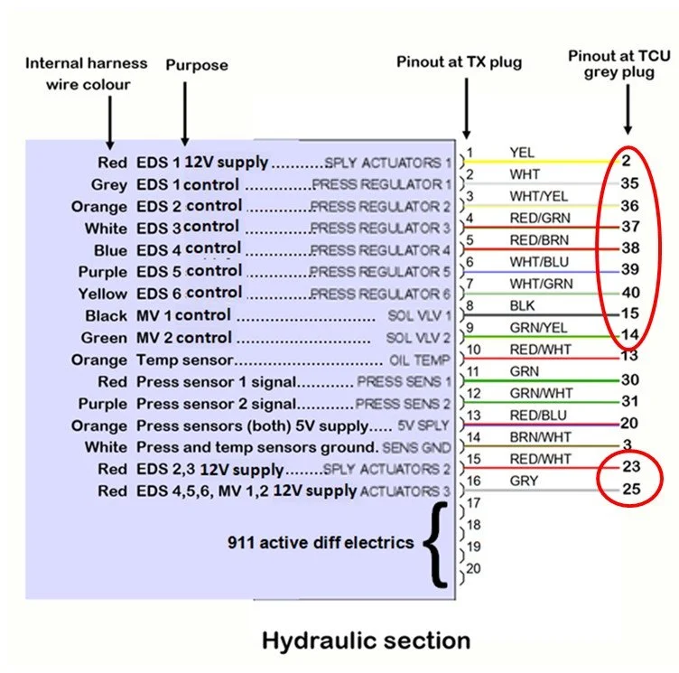
Refer to the wiring diagram above.
Solenoids get a 12V supply (these are the HSS voltages seen in PIWIS). This is then pulse width modulated (PWM) by the TCU to change power through the individual solenoid. There are four 4 separate 12V power supplies. The supply is switched fully on or off, and the output is controlled by PWM. In this way there are two methods of controlling solenoid power in the event of a fault. The supply switch and the PWM control on the output control.
If the TCU detects a problem with a something associated with a supply circuit, it will immediately switch off this supply. The solenoids are such that when no power is applied, the transmission will be in a limp and safe condition.
For example, if a problem is detected with the HSS2 circuit (clutch 2 and pressure), power is disabled to EDS2 and 3 that control these. It is now impossible to apply pressure to clutch 2, but the system pressure will default to maximum.
EDS 1 (clutch 1) gets its own supply at pin 2. (HSS 1)
EDS 2,3 (clutch 2 and pressure) at pin 23. (HSS 2)
EDS 4,5,6, MV1,2 (cooling and all shift control) at pin 25 (HSS 3)
I think the active diff control gets its own power supply but I have not tested this extensively to confirm. (HSS 4). EDS 7 (called pressure regulator 7 in PIWIS) controls the pressure in the active diff circuit. If not fitted, the current for pressure regulator 7 will be zero.
Voltage at pins 2, 23,25 should give you the current voltage provided by the car.
Control pins are PWM at 1000 Hz. The currents you see in PIWIS for each solenoid are just an average of the PWM control at the supply voltage.
PWM control duty factor can be measured for an individual solenoid at the control pin. Eg. Pin 35 for EDS 1. This can be measured to either ground or the supply voltage. So for EDS 1 this can be measured pin 35 – pin 2, or pin 35 to ground.
The measured duty factor is the inverse being applied to the solenoid. So if you measure 95%, this means the duty factor being applied to the solenoid is 5%.
Below are some examples of what you might see. Numbers are approximate. I haven’t tested this extensively, but I expect the duty factor will change based on supply voltage:
PIWIS indication = 50 mA is actually duty factor of 5%, but this is measured as 95% at the pins.
(EDS 1,2,5,6 after start at idle with P selected).
PIWIS indication = 600 mA is actually duty factor of 35 %, but this is measured as 65% at the pins.
(EDS 4 after start)
PIWIS indication = 850 mA is actually duty factor of 48%, but this is measured as 52% at the pins.
(EDS 3 after start)
Note the MV solenoids are not regulated and are a fully on/off type. They receive the full 12V supply when activated.
Normal resistances are:
EDS solenoids = 6.5 Ohm
MV solenoids = 13 Ohm
If you are interested more in valve body and solenoid operation, watch the “World’s best DCT – Part 2” video that I made. Go to the resources page. Link above.